Build Your First Flow
A step-by-step guide to manually creating a Flow in Nara
After learning the basics of using Nara and understanding the different parts of the Flow Page, the next step is to create a Flow from scratch by yourself. In this section, you will recreate the same Flow from the Deploy your First Flow (Quick Start) tutorial, but this time without using any templates.
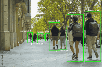
In this Flow, you will build an Quick Start: General Object Detection by displaying both the processed image and the detected object count on the Dashboard through Variable Nodes.
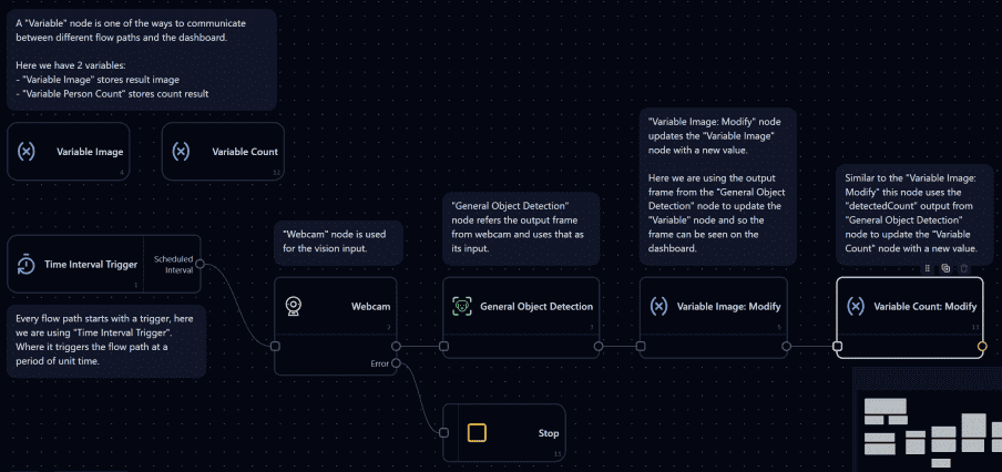
Flow Overview
Steps to Build the Flow Manually
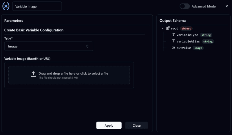
- Create the Variable Image Node:
Before creating the Flow Path, first create a Variable: Create Node since these Nodes act as intermediaries for transferring data between the Flow and the Dashboard. Configure the Node as shown below and rename it toVariable Image.
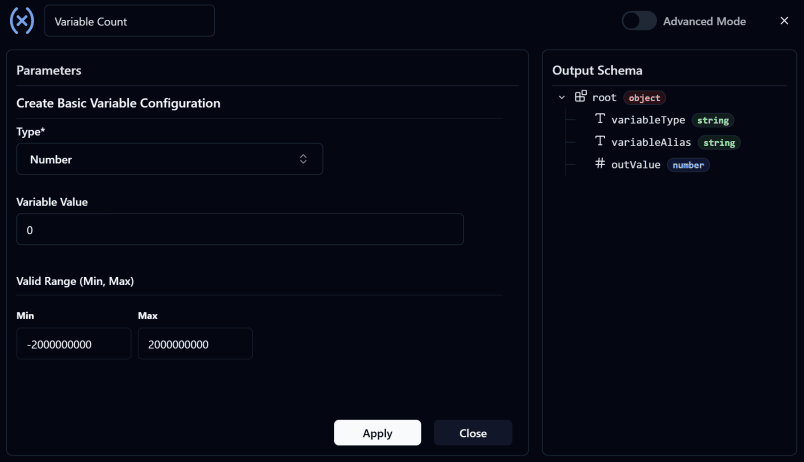
- Create the Variable Count Node:
This Node is used to store the number of detected objects in the image.
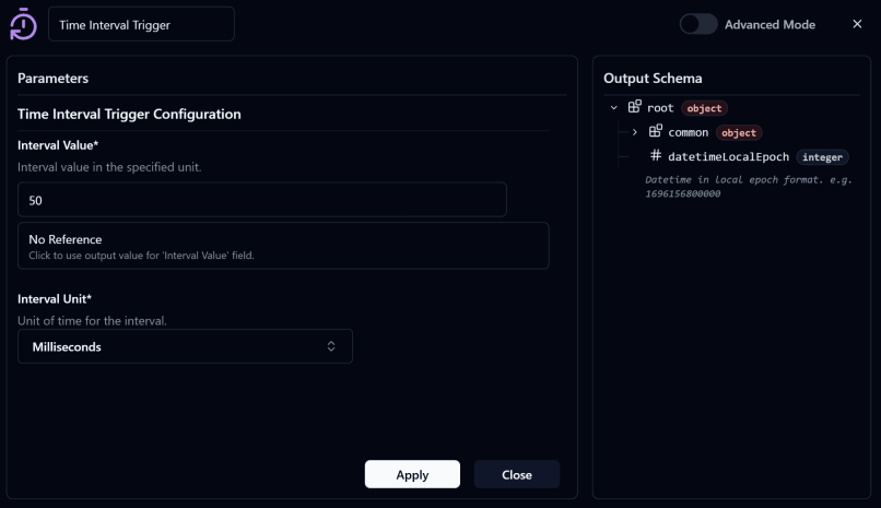
- Add a Time Interval Trigger:
Configure theInterval ValueandInterval Unitbased on how often you want the system to run. You can customize the settings as needed or follow the example below.
- Add a Webcam Node:
Configure the Node as shown below.
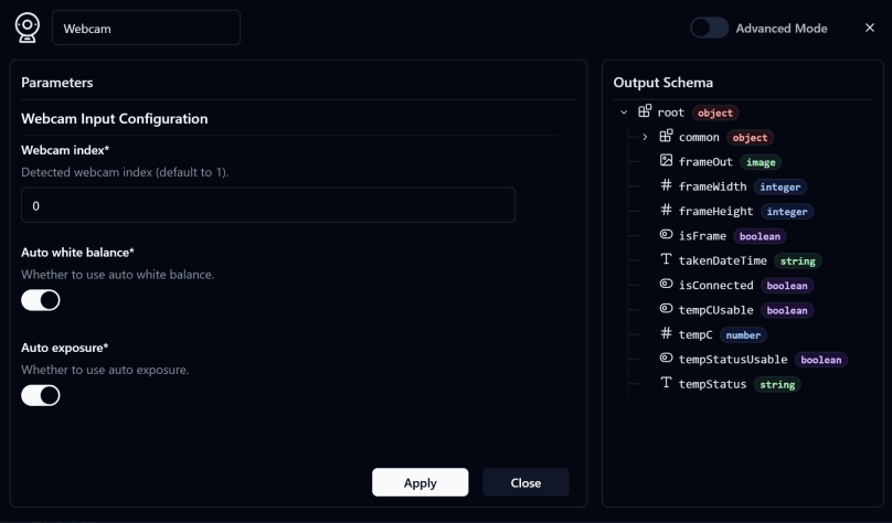
- By default, the Webcam Index is usually set to
0. - After configuration, connect the Input of this Node to the Output of the
Time Interval Trigger Node. - This Node captures frames from the webcam and sends them to the next Node for processing.
-
Add a Stop Node:
Connect the Error Output of the Webcam Node to the Stop Node to stop the Flow whenever an error occurs. -
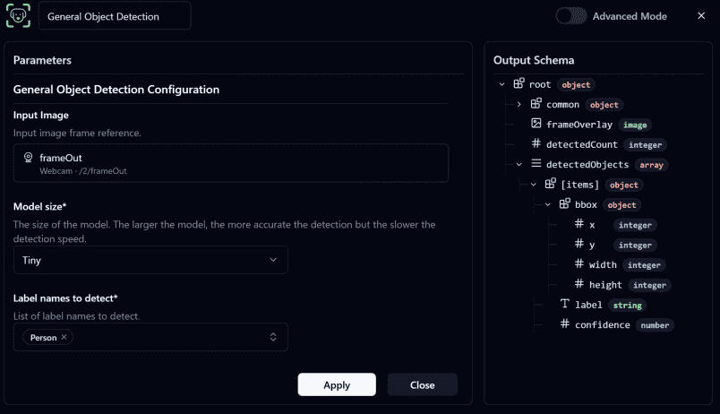
Add a General Object Detection Node:
Configure theInput Imageby referencing the Frame output from the Webcam Node. Then select the desiredModel Sizeand choose the objects you want to detect.
This Node analyzes the image and outputs:
- The processed image with detection results
- The number of detected objects
Note
Reference Input options are based on the connected upstream node and will only display outputs with matching data types.
For example, the Input Image field in the General Object Detection Node shows the frameOut option from the Webcam Node because the Webcam Node provides an image data type output.
- Add a Variable Modify Image Node:
Rename it toVariable Image: Modifyand connect it to the Output of the General Object Detection Node.
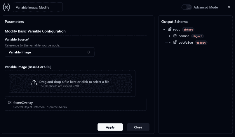
- Configure this Node to update the value of
Variable Imageusing the Output Frame from the General Object Detection Node. - The updated value will be displayed on the Dashboard through the
Variable ImageNode created in Step 1.
- Add a Variable Modify Count Node:
Rename it toVariable Count: Modifyand connect it to the Output of the General Object Detection Node.
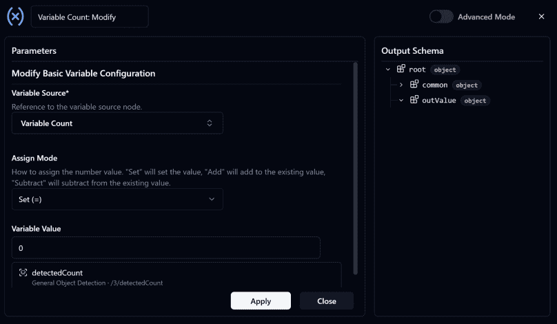
- Configure this Node to update the value of
Variable Countusing thedetectCountOutput from the General Object Detection Node. - The updated value will display the number of detected objects on the Dashboard.
-
Make sure all nodes are connected correctly as shown in the image below
-
Deploy the Flow
Steps to Build the Dashboard Manually
- Go to the Dashboard page and click
Editat the top-right corner. Then select the Image Frame Widget, drag and drop it onto the Dashboard, and resize it as needed.
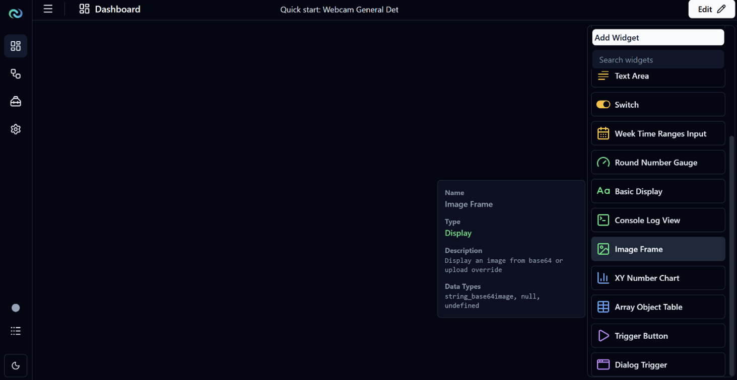
- Configure the Image Frame Widget by setting the
Data SourcetoVariable Imageso it displays the processed webcam image with object detection results.
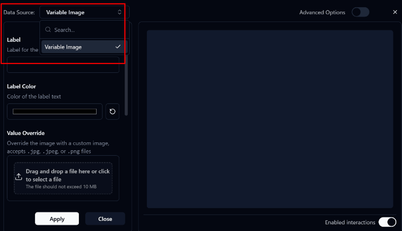
Note
The Data Source options in Widget Settings only display data that matches the widget's supported data type.
For example:
- Image Frame Widget displays Variables that support image data types such as
Variable Image - Basic Display Widget displays Variables that support numeric data types such as
Variable Count
- Add a Basic Widget to display the detected object count.
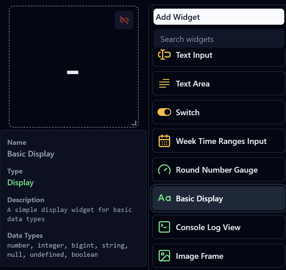
- Configure the
Basic Widgetand set theData Source > Variable Count.
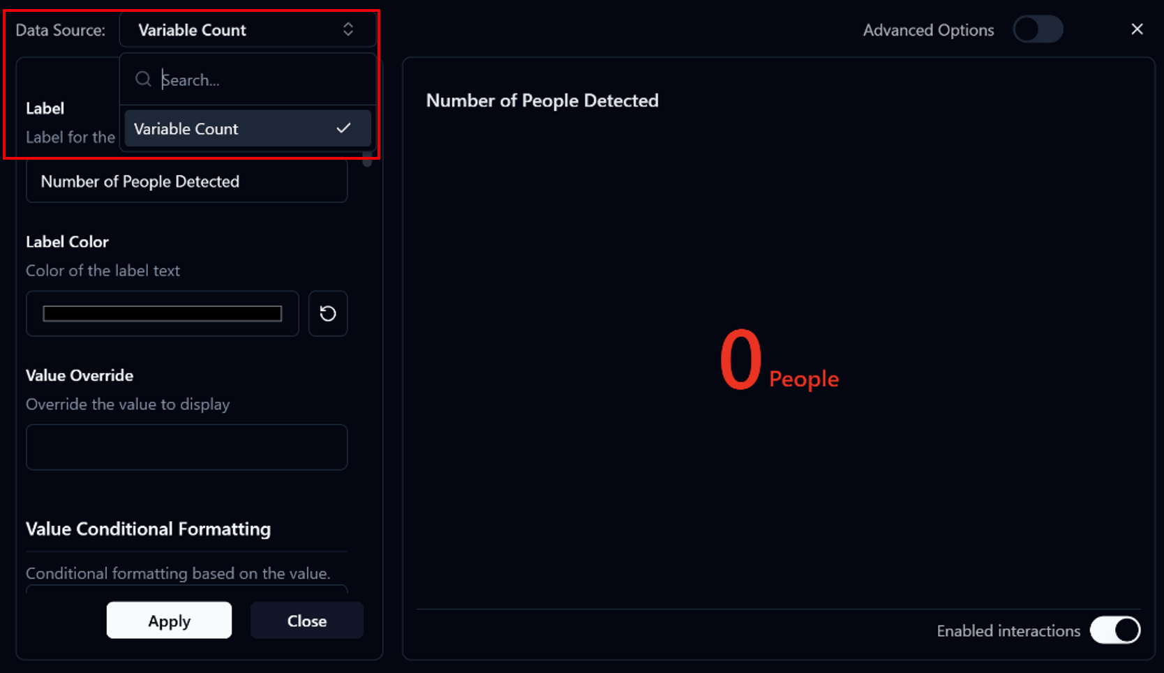
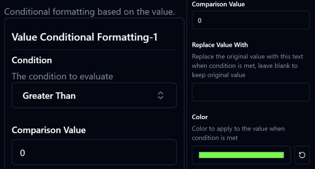
Set up Value Conditional Formatting with the following conditions:
> 0→ Display the count in green, indicating that a person has been detected= 0→ Display the count in red, indicating that no person has been detected
Congratulations! Your first Flow is complete