Custom Models
A guide to using Object Detection models trained in Reva within Nara
Objectives
You will learn how to:
- Export a trained model from Reva in the Nabrio Model
(.NAM)format - Create a Flow in Nara to receive images or videos and process them using an Object Detection model
- Create a Dashboard to display detection results in real time along with the number of detected objects
Note
This guide assumes that you have already trained a model in Reva. If you have not done so yet, please refer to Train Your First Model in Reva before proceeding.
Step 1 — Export a Model from Reva
Export a Trained Model
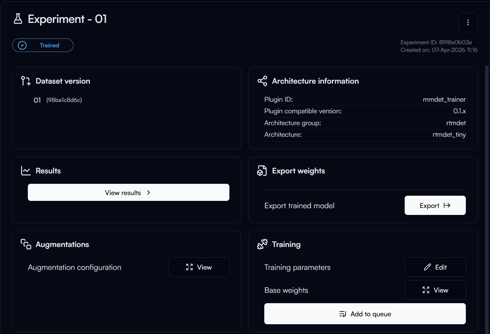
After training is complete, click the Export button in the Export Weights section to export the model for deployment.
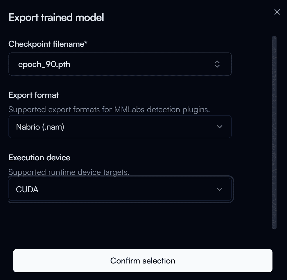
In the Export Trained Model form, configure the following settings:
- Filename of the Checkpoint: The name of the model checkpoint file. Checkpoints are named according to the epoch number. Review the training results and select the checkpoint with the best performance (for example, the highest mAP score). In most cases, this is the checkpoint from the highest epoch number. For this guide, use
90. - Nabrio Model: Select the export format. Choose
Nabrio (.nam), which can be deployed directly in Nara. - Execution Device: Select the device that will be used for inference. Choose the option that matches your deployment hardware (for example,
CUDAfor NVIDIA GPUs).
Then click Confirm Selection to begin the export process.
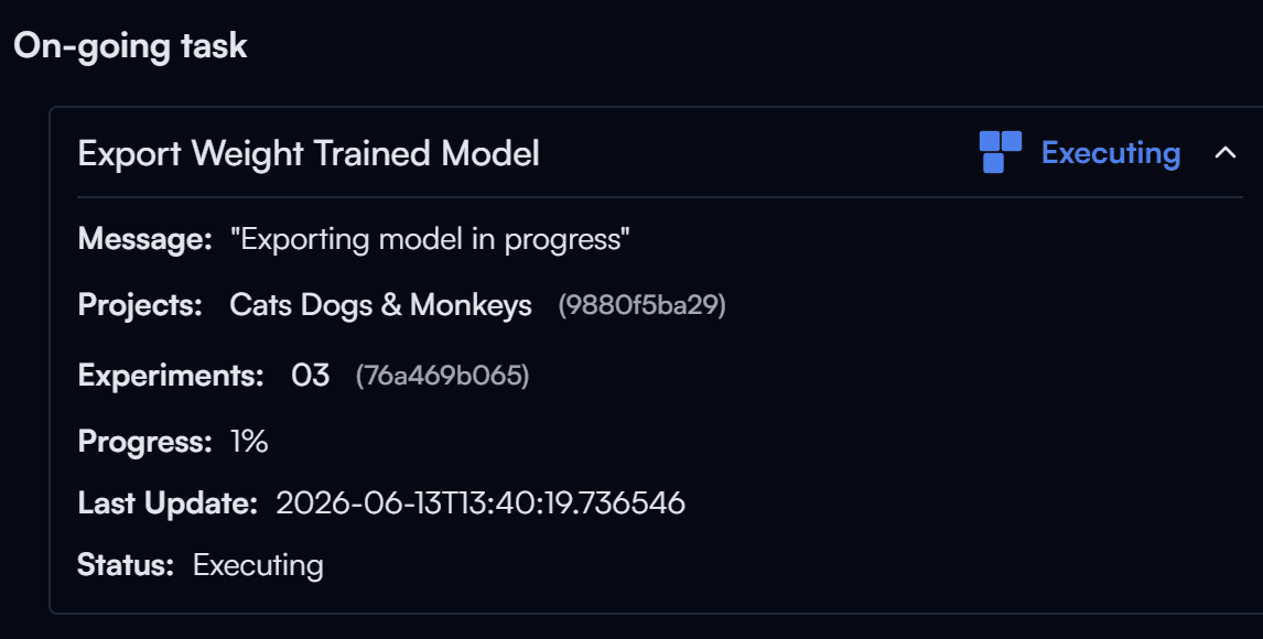
The export process may take a few moments.
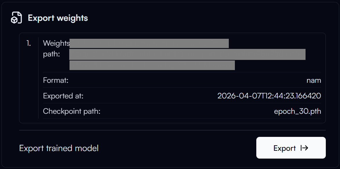
Once the export is complete, you can click Weight Path to copy the path of the exported model.
Step 2 — Create a Flow in Nara
In this Flow, we will create an automatic object detection system using Server Media Input. The processed image and the number of detected objects will be displayed on a Dashboard through Variable Nodes.
Flow Overview
Building the Flow Manually
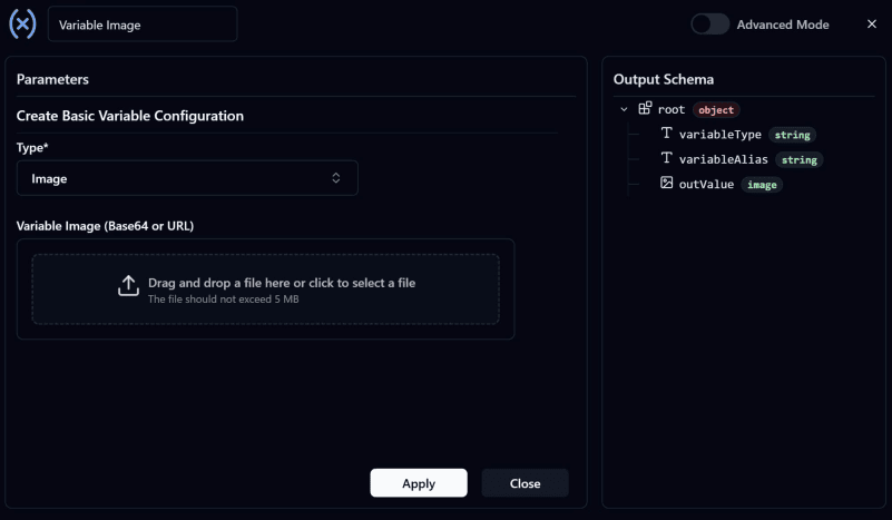
- Create a Variable Image Node: Before building the Flow Path, create a Variable: Create Node first. These nodes act as intermediaries for transferring data between the Flow and the Dashboard. Configure the node as shown in the image and rename it to
Variable Image.
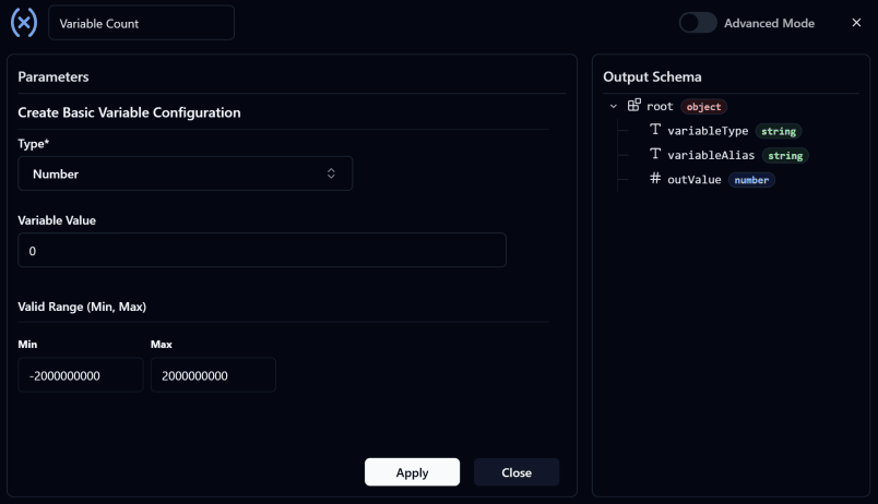
- Create a Variable Count Node: This node is used to store the number of detected objects in the image.
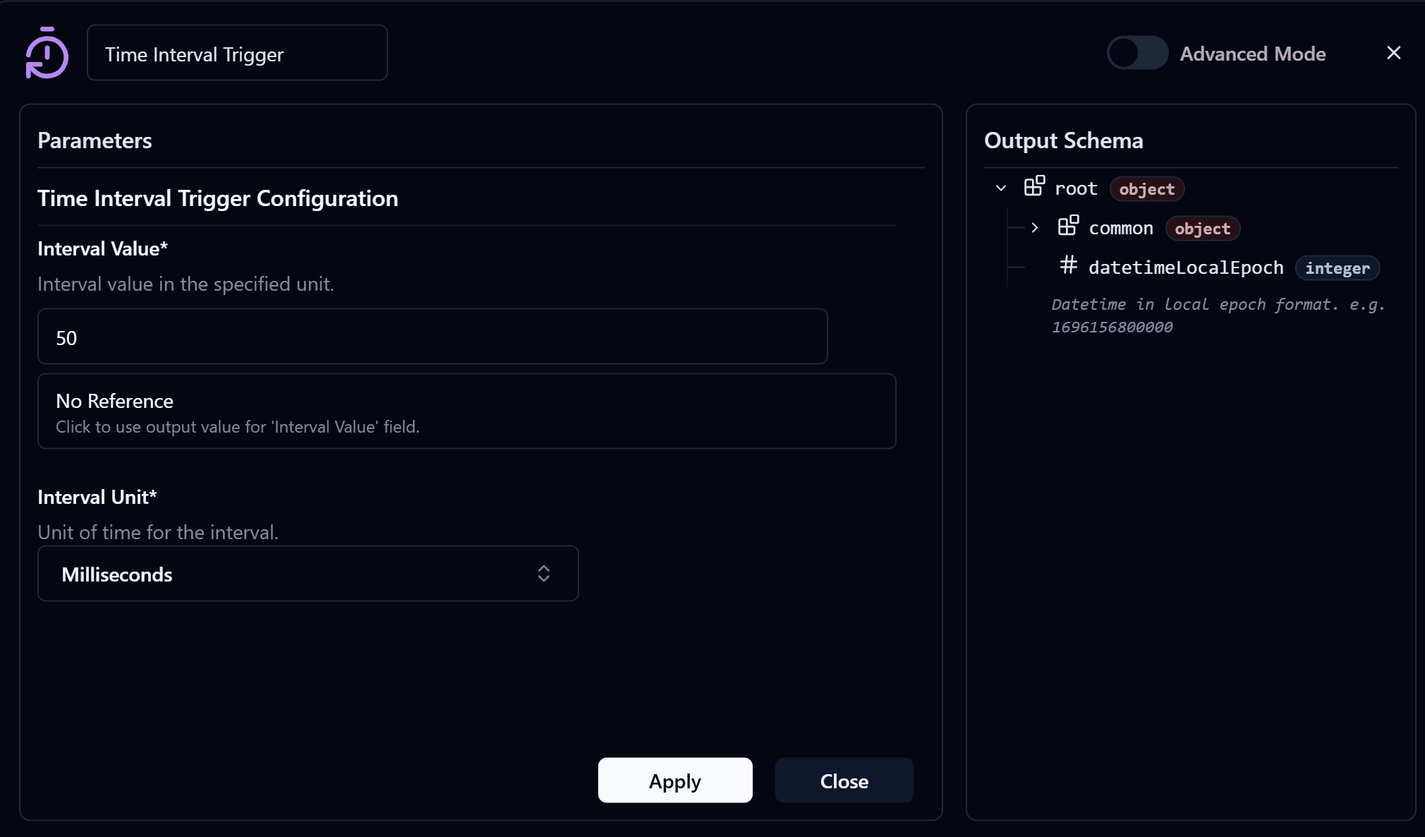
- Add a Time Interval Trigger: Configure the
Interval ValueandInterval Unitaccording to your requirements. Users may customize these settings as needed or use the configuration shown below.
- Add a Server Media Input Node and configure it.
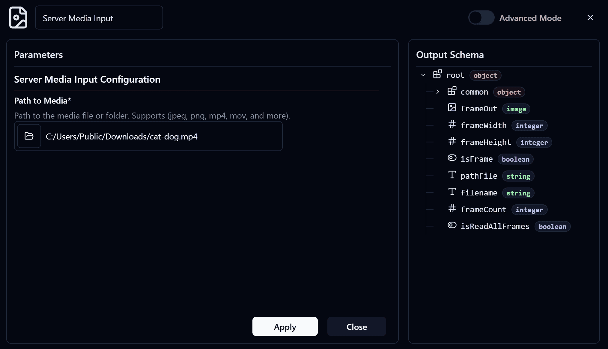
- Users can choose any media source, whether an image or a video. In this guide, a video source will be used. Once configured, connect the input of this node to the output of the
Time Interval Trigger Node.
Note
If you do not have a video available for testing, you can download a sample video here: Sample Test Video
Warning
This node will display a icon if the Media Source configuration is incomplete. Click the node and complete the required settings before proceeding.
-
Add a Stop Node: Connect the Error Output of the Server Media Input Node to the Stop Node to stop the Flow whenever an error occurs while receiving media.
-
Add an Object Detection Node: Configure the node's
Input Imageby referencing the frame output from the Server Media Input Node. Then select the model exported from Reva in Step 1. This node analyzes the image and produces two outputs: the processed image with detection results and the number of detected objects.
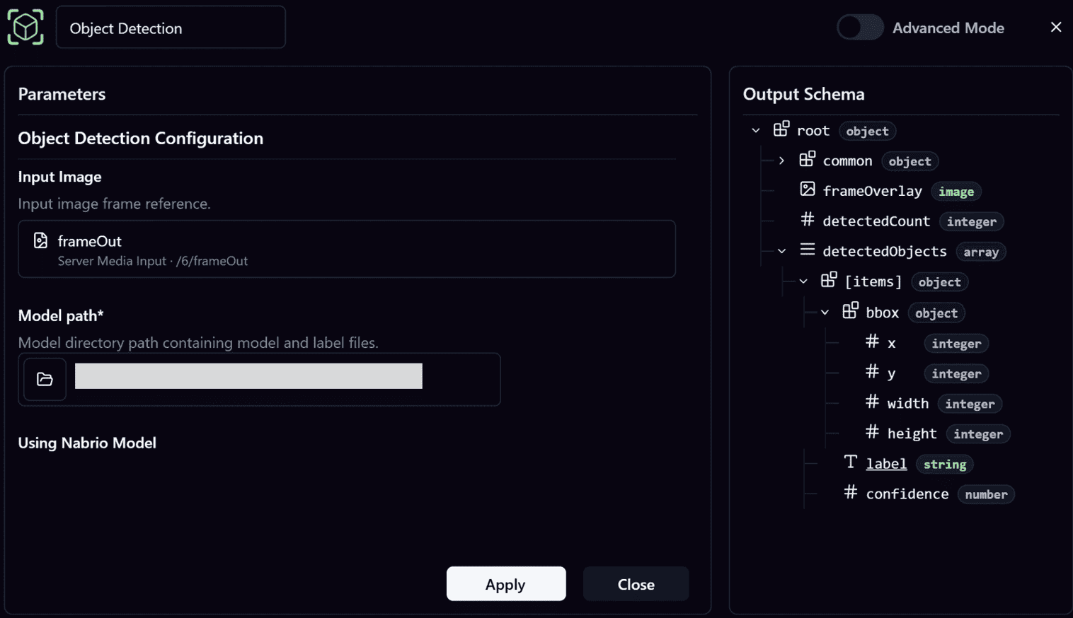
Note
The options available in Reference Input are determined by the connected upstream node and only outputs with matching data types will be displayed.
For example, the Input Image field of the Object Detection Node will display the frameOut output from the Server Media Input Node because it is an image data type output.
- Add a Variable Modify Image Node: Rename it to
Variable Image: Modifyand connect it to the output of the Object Detection Node.
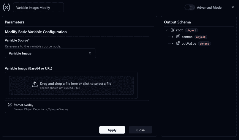
- Configure this node to update the value stored in Variable Image using the Frame output from the Object Detection Node.
- The updated value will be displayed on the Dashboard through the Variable Image Node created in Step 1.
- Add a Variable Modify Count Node: Rename it to
Variable Count: Modifyand connect it to the output of the Object Detection Node.
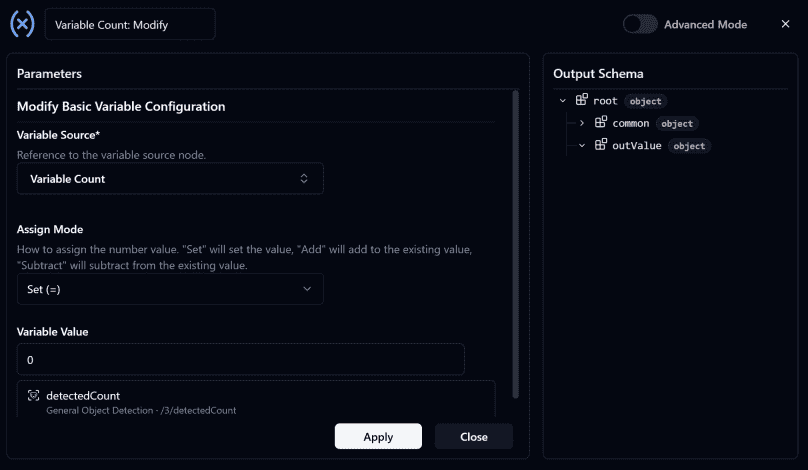
- Configure this node to update the value stored in Variable Count using the
detectCountoutput from the Object Detection Node. - The updated value will display the number of detected objects on the Dashboard.
- Verify that all nodes are connected correctly as shown below.
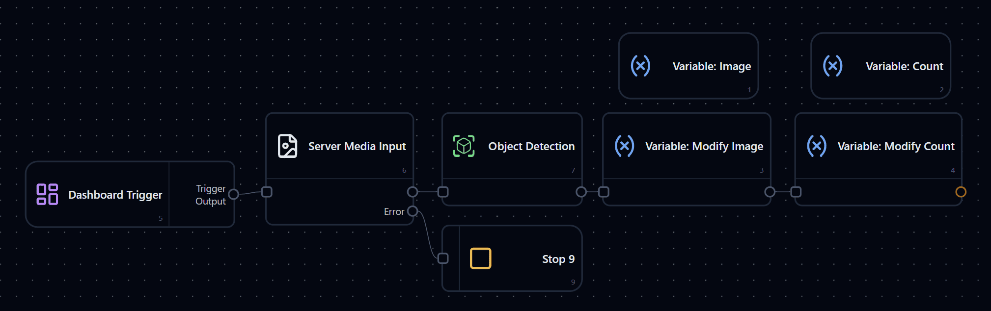
- Deploy the Flow
Step 3 — Create a Dashboard
Building the Dashboard Manually
- Go to the Dashboard page and click Edit in the upper-right corner. Then select an Image Frame Widget, drag and drop it onto the dashboard, and resize it as needed.
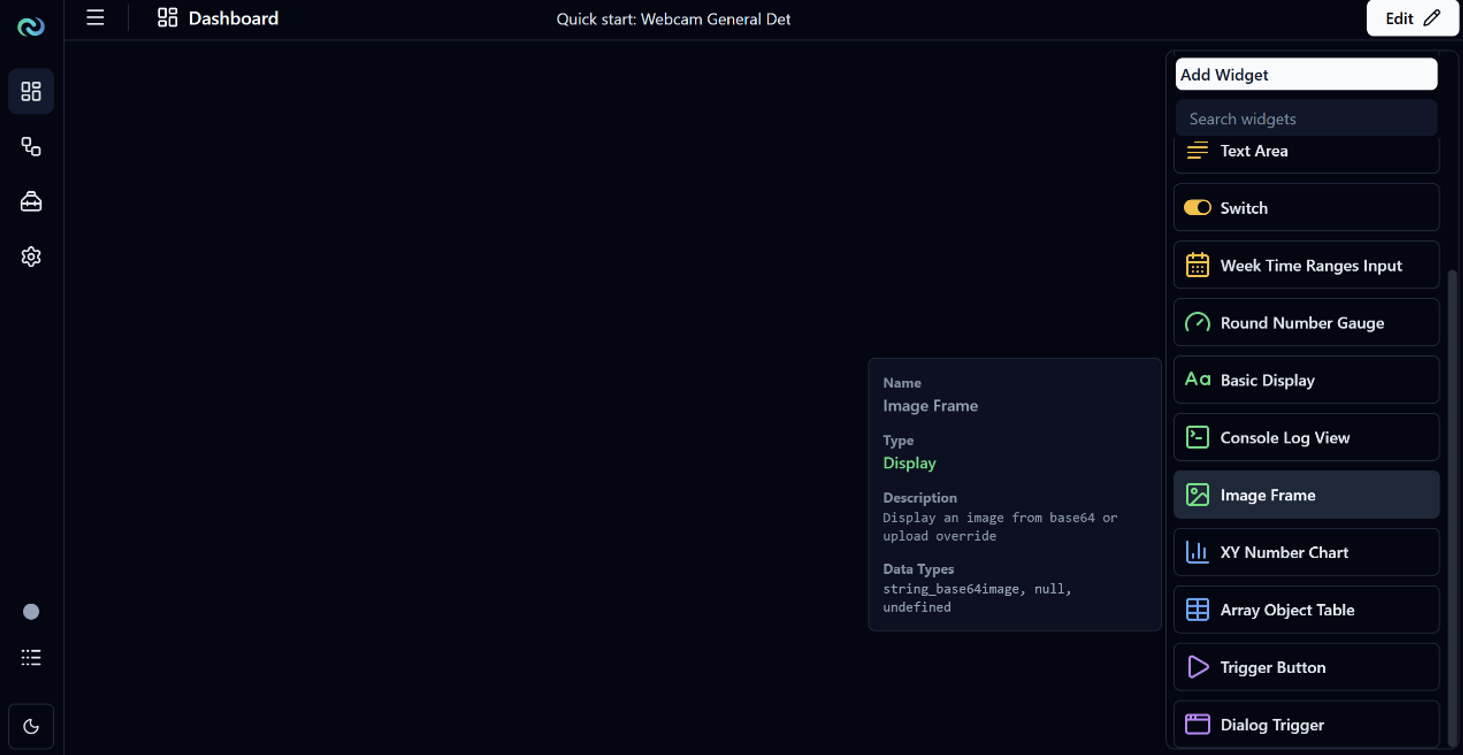
- Configure the Image Frame Widget by setting its Data Source to
Variable Imageso that it displays the image from the Server Media Input after Object Detection has been applied.
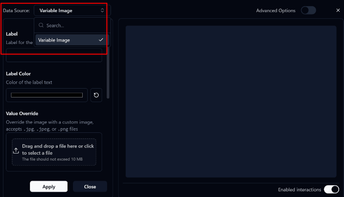
Note
The Data Source list in Widget Options only displays data sources whose data types are compatible with the selected widget.
For example:
- The Image Frame Widget displays variables that support the image data type, such as
Variable Image - The Basic Display Widget displays variables that support the numeric data type, such as
Variable Count
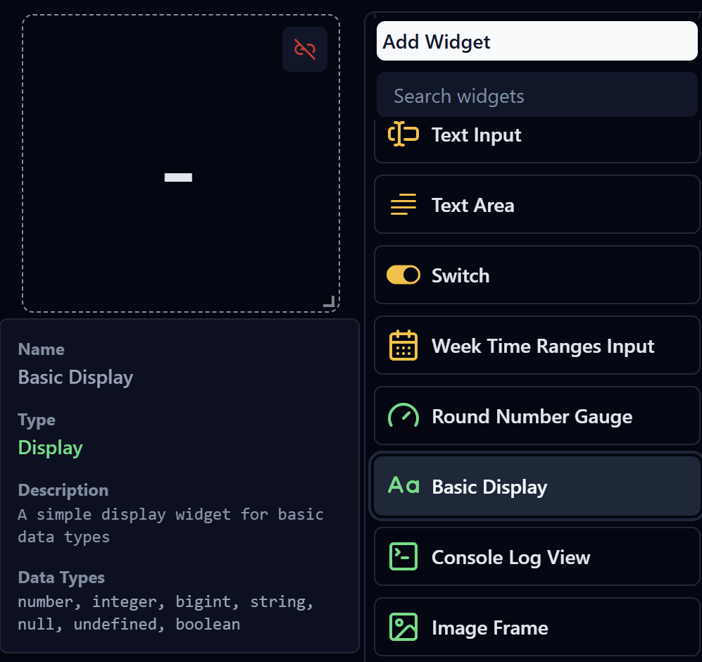
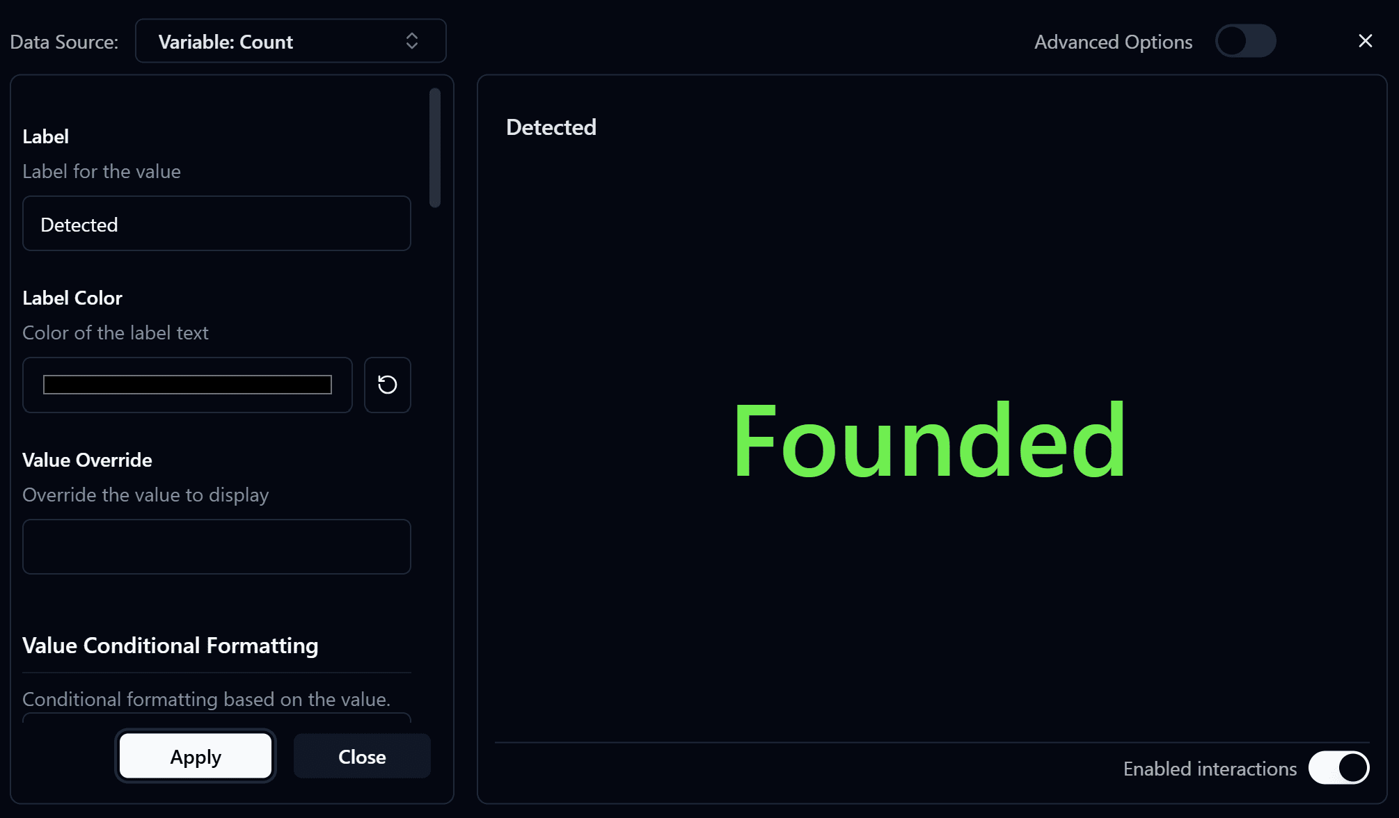
- Add a Basic Display Widget to display the detected object count.
- Configure the
Basic Display Widgetand selectData Source→Variable Count.
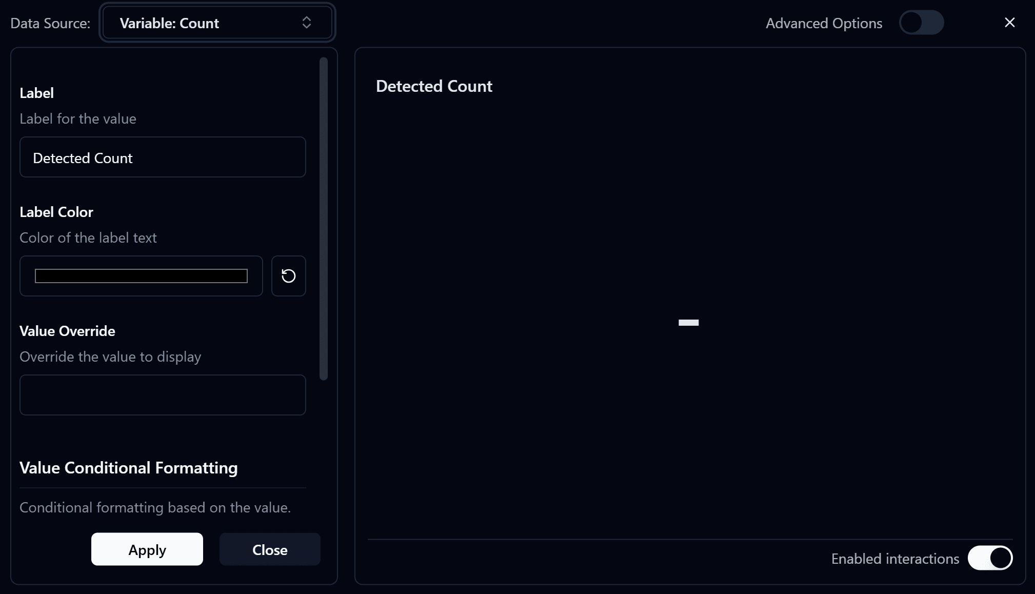
Configure Value Conditional Formatting with the following conditions:
> 0: Display the detected count in green, indicating that one or more objects have been detected.= 0: Display the value in red, indicating that no objects have been detected.
After completing the configuration, deploy the Dashboard. When you open the Dashboard page, you should see results similar to the image below.
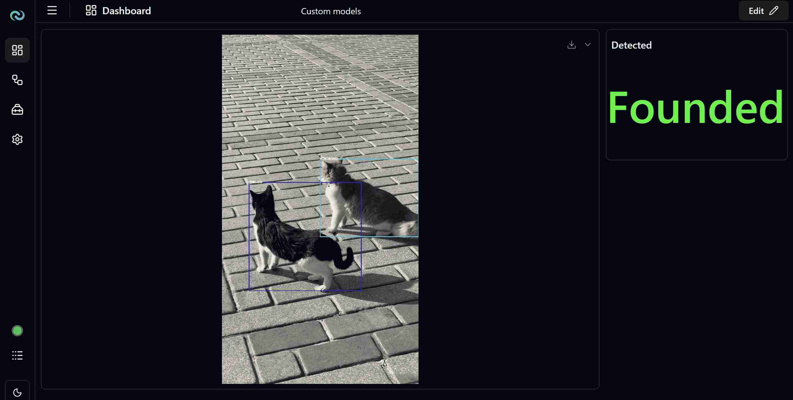
Congratulations! You have successfully learned how to use Nara together with Reva.